The first modern bearing isolator was patented in 1977. They were initially used in the food processing and chemical industries on pumps and mixers. Since the 1980’s they have been installed on most anything that rotates. Isolators protect the bearing housing from the introduction of liquids and debris (contamination ingress). By keeping the lube oil clean the bearing life is exponentially improved. Just as important the bearing isolators are also designed to keep the oil in the bearing housing of the pump. We occasionally receive complaints from the field regarding bearing isolator leakage. 99% of these issues are easy to solve. We have complied a list of the most common remedies and some added tips.
Causes of Bearing Isolator Leakage:
- 1.) Overfill of the bearing housing is the most common reason for oil leakage. The oil level should be at and no higherthan the middle of the sight glass. This "sighted” level should correspond with the middle of the lowest ball in the ball bearing set, either radial or thrust.
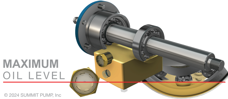
- Field Tip: It is important to understand that once the housing is overfilled it will take some time for the excess oil to be dissipated from the saturated isolator. In the interim it is important to continue cleanup of the expelled oil for several days or even weeks of running post overfill incident.
- 2.) Pump is not level. I recommend the use of a machinist level to check the pump and note the pump must be level in both directions (stem to stern and athwart-ships to describe it in nautical terms). Additionally, please make the distinction that “flat” is different from “level”.
- 3.) Wrong isolator “Case A”. For example, the isolator for the inboard end of a reverse vane impeller pump has a different style isolator than other style pumps. Field Tip: Reverse vane pumps adjust the axial clearance of the impeller to the seal chamber (stuffing box) by rotating the threaded bearing carrier on the inboard end. The bearing carrier contains the isolator and so it could be in any radial position as a result of setting the impeller clearance. For this discussion the inboard is defined as being closest to the coupling and outboard being farthest from the coupling.
- 4.) Wrong isolator “Case B”. For reasons other than #3 above, such as the wrong size or material. Please appreciate there are also different isolators for high/low temperature and or special applications such as a harsh chemical environment.
- 5.) Installed improperly or damaged during installation. See Instruction and Operating Manual (IOM).
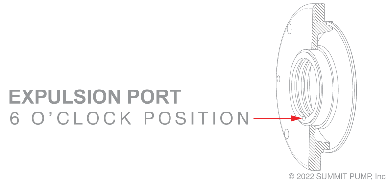
- 6.) Expulsion port is in the wrong location. It must be at the 6 o'clock position.
 - 7.) Fit and tolerance. The housing bore dimension (ID) and / or the outside diameter (OD) of the stator is incorrect. Refer to the IOM and/or factory for proper dimensions and tolerances.
- 8.) The isolator is installed properly but it is improperly moved at a later time. When adjusting the impeller clearance settings, or general maintenance and handling, care must be exercised so as not to damage the isolator. Sometimes the isolator stator separates from the rotor portion; in many cases you can simply push them back together.
- 9.) Re/installed without the “O”-ring on the OD of stator. (Not applicable all styles)
- 10.) Constant level oiler is set incorrectly (Cross nut adjustment is set to the wrong height… in this case too high) or it is installed in the wrong bearing housing penetration… or on the wrong side of the pump. Field Tip: Note constant level oilers are rotationally sensitive for proper operation. There is a correct and incorrect side of the pump to install them that depends on the direction of rotation of the pump.
- 11.) Over-pressurization of the bearing housing. This issue can easily get complicated, but a simple explanation is that the pressure of contained air will rise and fall with temperature. Think “ideal gas” laws. Field Tip: With higher pressure in the bearing housing and the pump operating the resulting oil level can appear to be too low in the sight glass, which will erroneously invite the addition of oil and consequential overfill. Another issue is that the higher pressure can force oil level below the minimum level and the bearing and oil will overheat. The oil will turn black.
- 12.) Excessive pipe strain. The resultant forces and moments of suction and discharge piping induced stress will cause the bearing bore and consequently the bore for the isolator device to be out of round, nonconcentric or noncongruent. The condition will likely create an offset centerline with the sister bearing and isolator. Field Tip: Check for pipe strain by placing dial indicators (or lasers) in two planes on the coupling hub. Release the bolts on one of the pump flanges…. if the dial indicator moves more than 0.002 inches then there is excessive pipe strain. Repeat for the other flange. Correct the cause of the stress before proceeding.
- 13.) Excessive vibration. The vibration can be due to cavitation, air binding, impeller imbalance, surging and or operating outside of the allowable operating area.
- 14.) Misalignment of the driver to the pump.
- 15.) Drive train component such as a rotating coupling (spinning in the semi-enclosed space of an enclosed OHSA guard) is too close to the external face of the isolator. In rare cases and mostly on larger frame (higher horsepower) pumps, a low-pressure area can be created (by the air velocity also know in this case as windage). The low-pressure area creates a differential pressure outside of the bearing housing near the face of the bearing isolator. Consequently the oil can be picked up and moved with the air flow “windage”. To correct this situation you can distance the coupling and OSHA guard from each other and or from the isolator face. An alternate solution in many cases is to just use a bigger OSHA guard or incorporate perforated mesh metal on the ends of the guard.
- 16.) Other miscellaneous reasons. Occasionally oil is leaking out of the pump, but it is not due to the bearing isolator. During the repair and maintenance cycles sometimes the bearing housing gaskets are omitted, manufactured in the incorrect material and/or of wrong dimension. In rare instances the bolts may not be properly torqued.
- 17.) Oil sight glass is located at the incorrect height(manufacturing or repair defect). While not a leak issue, but of interest on this subject. We have witnessed the end user installing the (ANSI) pump next to a wall with the oil sight gage glass (indicator) on the wall side of the pump. To achieve direct line of sight to the indicator, the operator removed the sight gage from the port side of the pump and relocated it on the other side (starboard) of the bearing housing.On most ANSI pumps there is a normally plugged penetration where the finned oil cooler would be located, if used. Both the oil cooler and the sight glass penetrations are sized at 1" NPT. However, the centerline of the cooler penetration is at a slightly lower level (in this case 2") than the sight glass penetration to allow for shaft clearance. The result is that the new corresponding oil level will now be too low and consequently incorrect. The resulting bearing life will be severely compromised due to inadequate lubrication.
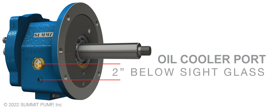 Note that some pump manufacturers have penetrations on both sides of the pump bearing housing for the sight glass installation on either or both sides. Note that some pump manufacturers have penetrations on both sides of the pump bearing housing for the sight glass installation on either or both sides.
See my Pumps & System's article for more detailed information on this subject.   |
|
